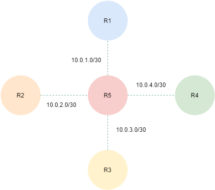
Ever get a little confused from time to time when configuring a Router or a Switch when it comes to the default route vs. the default gateway.? Don’t worry I think we all have at one time or another. The fact of the matter is only two of them have similar purpose while the other the Default Gateway is completely different. Lets break all three of them down with this vary simple configuration.

The Defaults
- The Default Network
- The Default Route
- The Default Gateway
Routing vs. Switching
One way to look at it would be to consider what does a Router need as opposed to a Switch..? The simple answer is Router’s look at Layer 3 Header information when forwarding packets, and Switches examine the Layer 2 Header when forwarding frames. However Layer 3 switches behave similar to routers it comes to forwarding packets between different networks or VLANS. With a routers however there are basically 3 options while Layer 2 switches only have one.
- A static default network
- A static default route
- A dynamic default route
Routers R1 . . . R4 Loopbacks
- R1 Loopback0 = 172.16.1.1 255.255.255.240
- R2 Loopback0 = 172.16.2.1 255.255.255.240
- R3 Loopback0 = 172.16.3.1 255.255.255.240
- R4 Loopback0 = 172.16.4.1 255.255.255.240
One of the most often overlooked features of a Router is it’s ability to forward packets at Layer 3. Of course we all know this because it’s inherently on by default. This inherent feature can be disabled. For example lets take a quick look at the routing table on the R5 Router.
R5#show ip route connected
Gateway of last resort is not set
10.0.0.0/30 is subnetted, 4 subnets
C 10.0.2.0 is directly connected, Serial0/1
C 10.0.3.0 is directly connected, Serial0/2
C 10.0.1.0 is directly connected, Serial0/0
C 10.0.4.0 is directly connected, Serial0/3
R5#
We can see from the above output that there are a total of 4 connected routes each pointed at their respective remote Router R1, R2, R3, and R4. This is to be expected since we have 4 connected interfaces. But what if disable Layer 3 routing on the R5 Router.
R5#configure terminal
R5(config)#no ip routing
R5(config)#end
R5#
Now lets take a look at the current state of the routing table on the R5 Router without ip routing enabled. We can clearly see that the routing table no longer shows the 4 connected routes to each remote.
R5#show ip route
Default gateway is not set
Host Gateway Last Use Total Uses Interface
ICMP redirect cache is empty
R5#
Check it out we now have a Router that is not willing to participate in forwarding packets, and more importantly notice the difference between the routing tables. So without ip routing enabled we no longer have a “Gateway of last resort” set and instead we have a “Default gateway is not set“. Now the Router is acting more like a Layer 2 Switch as opposed to a Router. When configuring a Layer 2 Switch with a management ip address of one or more of the VLAN’s you to be sure and set the “Default gateway” in much the same way you would set one on a Server or PC.
Dynamic Routing Protocols
One way to achieve a default route via dynamic routing is to simply advertise one. The following basically advertises a quad 0 or default route throughout the routing domain stating that if no other route is in your routing table simply send the traffic to me. Lets re-enable ip routing on the R5 once again, and configure / advertise the “Gateway of last resort” throughout the routing domain.
R5#configure terminal
R5(config)#
R5(config)#interface loopback 0
R5(config-if)#ip address 1.1.1.1 255.255.255.255
R5(config-if)#exit
R5(config)#ip route 0.0.0.0 0.0.0.0 loopback0
R5(config)#ip routing
R5(config)#router eigrp 1
R5(config)#eigrp router-id 1.1.1.1
R5(config)#network 0.0.0.0 0.0.0.0 - - - - - Run EIGRP on all 4 interfaces
R5(config)#no auto-summary
R5(config)#end
R5#
Now that we have EIGRP up and running lets take a look at which interfaces its running on.
R5#show ip eigrp interfaces
IP-EIGRP interfaces for process 1
                  Xmit Queue Mean Pacing Time Multicast  Pending
Interface  Peers Un/Reliable SRTT Un/Reliable Flow Timer Routes
Se0/0      0     0/0        d0    0/1         0          0
Se0/1      0     0/0         0    0/1         0          0
Se0/2      0     0/0         0    0/1         0          0
Se0/3      0     0/0         0    0/1         0          0
Now lets take a final look at the routing table on R5…
R5#show ip route

Gateway of last resort is 0.0.0.0 to network 0.0.0.0

     1.0.0.0/32 is subnetted, 1 subnets
C     1.1.1.1 is directly connected, Loopback0
     10.0.0.0/30 is subnetted, 4 subnets
C       10.0.2.0 is directly connected, Serial0/1
C       10.0.3.0 is directly connected, Serial0/2
C       10.0.1.0 is directly connected, Serial0/0
C       10.0.4.0 is directly connected, Serial0/3
S*   0.0.0.0/0 is directly connected, Loopback0
We can clearly see that the “Gateway of last resort” is now set and we have a S* static route in the routing table pointed at the local Loopback 0 interface. The local Loopback 0 interface of course serves no purpose since it’s actually a route to nowhere, however for the purpose of this post it works.
I hope you found this post helpful and informative. Be sure to let me know what you think by leaving suggestions, and feedback in the comments section below. You can find out more about these and other articles be checking out recent posts and archives. To learn more about me be sure to check out the About page. And as always thanks again for visiting The Packet.
